Signal Flow
<texit>\index{Signal Flow|(}</texit> For a correct understanding of what happens in the software-radio and where to insert a new module, it is very good to have an overview of the signal-flow that goes through the radio. As of the writing of this chapter, new hardware is being installed in our lab. For this reason, this chapter is seperated into three sections:
- Common: the common signal-flow
- ICS-hardware: the signal-flow specific to the ICS-cards
- STM-hardware: the signal-flow specific to the STM-cards
Common
 |
|
The common part of the signal-flow
(signal_common.ps) |
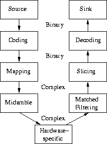
In figure <ref>fig:signal_common</ref> you see an overview of the most common architecture when building a software-radio. On the left-hand side you see the transmitting modules while on the right-hand side the receiving modules are located. Each transmission is built around a slot which is a constant time-slice in the transmission.
Transmitting
The most common implementation starts with two blocks that have bits as output. The Source may be anything, from a pseudo-random sequence to a part of a network-transmission.
These bits go through a Coding block, where redundant information is added, in order to assure some error-resistance when receiving the data. The ouput of this operation are again bits. For the coding we have ldpc-codes, convolutional-codes or spreading-sequences which allow also for to seperate multiple users if they send at the same time-instant.
 |
|
QPSK signal space
(qpsk_space.ps) |
|
(ps) |

 |
| fig:midamble(figureend_position_of_the_midamble.ps) |
 |
|
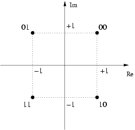
into symbols. The most common
mapping is a QPSK-mapping, where two bits define one symbol, as can be seen in figure
fig:qpsk-signal-space. The mapper-module supports also other
PSK-mappings or QAM-mappings. But commonly the QPSK-mapping is used.
In the middle of this block, a test-sequence is inserted which is called
(ref_._the_mapper-module_supports_also_other_psk-mappings_or_qam-mappings._but_commonly_the_qpsk-mapping_is_used._in_the_middle_of_this_block_a_test-sequence_is_inserted_which_is_called_.ps) |
 |
|
, because of it's position in the block, as can be seen in
figure fig:midamble. The goal of this test-sequence is to be able to
estimate the channel at the receiving end and to perform a matched filtering
afterwards, cancelling out any effects due to the channel.
Once these four basic operations are done, the block composed of complex
symbols goes through the hardware-specific part.
====Receiving====
Out of the hardware-specific part, we get again a block composed of complex
symbols. If we have a flat fading channel with only one tap, that is a direct
line-of sight, as well as a perfect synchronisation between the sending and
the receiving part (which is usually NOT the case), then this receivd symbols
would be the same as the sent ones.
In common transmissions, this is not the case. For this reason we have the
(ref_._the_goal_of_this_test-sequence_is_to_be_able_to_estimate_the_channel_at_the_receiving_end_and_to_perform_a_matched_filtering_afterwards_cancelling_out_any_effects_due_to_the_channel._once_these_four_basic_operations_are_done_the_block_composed_of_complex_symbols_goes_through_the_hardware-specific_part._receiving_out_of_the_hardware-specific_part_we_get_again_a_block_composed_of_complex_symbols._if_we_have_a_flat_fading_channel_with_only_one_tap_that_is_a_direct_line-of_sight_as_well_as_a_perfect_synchronisation_between_the_sending_and_the_receiving_part_which_is_usually_not_the_case_then_this_receivd_symbols_would_be_the_same_as_the_sent_ones._in_common_transmissions_this_is_not_the_case._for_this_reason_we_have_the_.ps) |
 |
|
, where the midamble from the sending chain is used
to estimate the channel-parameters. Using these channel-parameters, one can
improve the received quality of the signal. The output of this module is the
filtered signal without the midamble. This module usually produces also
information used by other modules, such as
(where_the_midamble_from_the_sending_chain_is_used_to_estimate_the_channel-parameters._using_these_channel-parameters_one_can_improve_the_received_quality_of_the_signal._the_output_of_this_module_is_the_filtered_signal_without_the_midamble._this_module_usually_produces_also_information_used_by_other_modules_such_as_.ps) |
 |
|
or
(or_.ps) |
 |
|
of
the signal.
Now that the received signal is filtered, it is ready to be sliced.
(of_the_signal._now_that_the_received_signal_is_filtered_it_is_ready_to_be_sliced._.ps) |
 |
|
denotes the fact of taking a hard decision on the received
symbols. For a QPSK-signal, the quadrant of the symbol gives directly the two
bits. If the signal-alphabet is bigger, one has to calculate the distances
between the received symbol and all possible emitted symbols, and then taking
the smallest distance. A hard decision is usually the worst thing to do.
For example the LDPC-decoder takes the complex symbols directly from the
matched filter and achieves much better results.
After the slicing, we have again a block of bits, which run through the
(denotes_the_fact_of_taking_a_hard_decision_on_the_received_symbols._for_a_qpsk-signal_the_quadrant_of_the_symbol_gives_directly_the_two_bits._if_the_signal-alphabet_is_bigger_one_has_to_calculate_the_distances_between_the_received_symbol_and_all_possible_emitted_symbols_and_then_taking_the_smallest_distance._a_hard_decision_is_usually_the_worst_thing_to_do._for_example_the_ldpc-decoder_takes_the_complex_symbols_directly_from_the_matched_filter_and_achieves_much_better_results._after_the_slicing_we_have_again_a_block_of_bits_which_run_through_the_.ps) |
 |
|
, where an algorithm tries to correct for transmission errors.
As noted before, decoding on bits is not ideal, but it is what happens in
most school-book examples
(where_an_algorithm_tries_to_correct_for_transmission_errors._as_noted_before_decoding_on_bits_is_not_ideal_but_it_is_what_happens_in_most_school-book_examples.ps) |
 |
|
The signal preparation for ICS
(hardware-base.ps) |
 |
|
The signal preparation for STM
(hardware-passband.ps) |
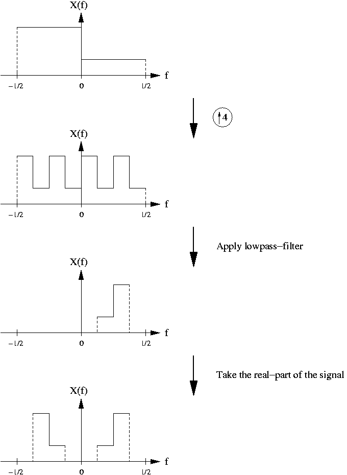
The figures <ref>fig:hardware-baseband</ref> and <ref>fig:hardware-passband</ref>
depict the steps done to the signal from the fourier-transform point of
view. The range of the fourier-transform has been chosen to be
 , but one could have
 or
or
 without changing the meaning at all.
ICS-hardware
<texit>\index{Hardware!ICS}</texit>
In figure <ref>fig:hardware-baseband</ref>, you can see the preperation necessary for sending the signal to the ICS-hardware. The signal is first upsampled by a factor of two. This is done by inserting a zero in between two complex symbols.
Next we apply the lowpass RRC-filter and now we have a signal that occupies half the bandwith, but at double the symbol rate. Thus, we didn't loose information.
On the receiving side, exactly the contrary needs to be done: first we apply the RRC-filter, then we downsample by a factor of two. The filtering is necessary, as there might be some other signal next to ours. And, because the reception sample-rate is twice the symbol-rate, we have to downsample by a factor of two.
Philips-hardware
<texit>\index{Hardware!Philips}</texit>
The latest hardware that is not yet installed has been developed by Philips. It contains the A/D- and D/A-converters directly on the same board as the RF-part. The connection to the PC is made via two SCSI-cables, and the PCI-card only contains simple glue logic to put the data on the PCI-bus or to read it from there.
This hardware works at 1.9GHz and has a bandwith of 5MHz.
STM-hardware
<texit>\index{Hardware!STM}</texit>
Looking at figure <ref>fig:hardware-passband</ref>, you can see that for the STM-hardware, we need to upsample by a factor of four. The filter chosen for the pulse-shaping is a passband-filter, that has a bandwith of 1/4.
Because the hardware accepts only real samples, we can't keep the signal at baseband, as a loss of the signal would happen. You can see that by taking the real-part of the signal, it gets mirrored at the axis. If you do this with a baseband signal, information loss occurs.
These three operations are done using advanced MMX-operations that manage to take advantage of the special structures of the filters and the signal. <texit>\index{Signal Flow|)}</texit>