Important Modules
In this chapter you'll learn about some of the most important modules in the software-radio. They represent the basic functionality and should be known by everyone that wants to handle the software-radio.
STFA
<texit>\index{STFA}</texit> STFA stands for Slot To Frame Allocator. Its main purpose is to map the RX- and TX-slots to the correct moment in time. First of all you need to understand the principles of a slotted TDD transmission using frames. In figure <ref>fig:stfa_frames_slots</ref> you can see a transmission of 3 frames. Each frame takes the same amount of time. Normally the frame-structure stays the same during the transmission. Of course this wouldn't be the case in a multi-user environment, where a frame contains the structure of the up- and downlink slots, which would change during connection and disconnection of users.
 |
|
The frames and slots
(stfa_frames_slots.ps) |
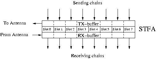
The STFA represents this frame-structure. It is a module with inputs and outputs, where is the number of slots per frame. The purpose of the STFA is to calculate the slots so that they are sent at the correct moment in time. To understand figure <ref>fig:stfa_in_out</ref> correctly, it helps to imagine yourself the STFA as a representation of the channel. So the inputs of the STFA are the inputs to the channel, which corresponds to the TX-part. The outputs of the STFA are what comes out of the channel, which is the RX-part.
 |
|
Inputs and outputs of the STFA
(stfa_in_out.ps) |
Internally, the STFA has two large sample-buffers that hold one complete frame in memory. One buffer is read continously 1) from by the D/A converter, while the other buffer is written to continously 2) by the A/D converter. For this reason, it is important that the result of one slot is computed before the D/A converter needs it. It is also important that a RX-slot is processed before the next frame.
Synchronisation
A common problem in a slotted TDD-environment is the synchronisation of two
stations. If we consider two participants in a communication, called BS and MS
(for Base Station and Mobile Station), one has to define at what instant in
time the first frame starts. If we call this time-instant
 , then
all consecutive frames will start at
 where is a positive integer and
 is the time-duration of one
frame. This also defines all slots, as
 with
with  the time-duration of one slot and
 .
.
We can't know beforehand
 , and also
 is only known up to a certain
 , because of clock-drifts between the two stations. One
solution is to send a synchronisation-signal in slot 0, so that one can know
 for every frame. Then we can find
 for all
the other slots of the frame, supposing that the error in
 is negligible when calculating the time-instants of one slot.
 |
|
A typical set-up of the STFA
(stfa_typical.ps) |
This setup is shown in figure <ref>fig:stfa_typical</ref>. In a real system, the MS
starts out with synchronisation modules attached to all its STFA-outputs. The
reason for this is that upon startup, we don't have any information about
 , so we have to expect the synchronisation-signal on any slot.
Once the synchronisation-signal is found on a given slot, the buffers are
adjusted so that the synchronisation-signal falls into
  . Then, each
time
  is received, the buffer is adjusted again, so that all
  are accurate and in synchronisation with the BS again.
Important Parameters
There are three groups of parameters in the STFA:
- Structural which define the size of the different parts of the STFA
- Timing everything that got to do with preparation of slots and synchronization
- RF the parameters of the RF-part are also reflected in the STFA
Structural
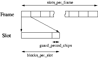
These are quite important, as they define the basic structure and size of the STFA. You can't change these parameters once the STFA has been started, as the DMA-transfer would be disturbed greatly by this. An overview of the parameters is given in figure <ref>fig:stfa_size_params</ref>.
 |
|
The different size-parameters
(stfa_size_params.ps) |
The blocks_per_slot parameter has a unit of 128 symbols. By taking the default value of 20, this gives a slot-length of 2560 symbols. Substracting the guard-period, we get a useable slot-length of 2470 symbols.
To make things even more complicate, the total number of blocks has to be a multiple of 16. This is due to the fact that the DMA-transfer is done in blocks with a size of 16 * 128 symbols 3). Taking a smaller block-size for the DMA-transfer would result in more interrupts and thus a higher system-load.
As we have a TDD-system, TX and RX slots are stacked up in time. Without any special handling, the RF-system would have to be able to switch off the transmit-chain from one symbol to another. Because this is very difficult to do, a guard-period has been inserted. During this time, the state of the RF-cards is not defined, and no useful data is transmitted.
Timing
Usually you don't have to change these parameters. They are taken into account by the synchronisation-macro module.
Attaching Chains
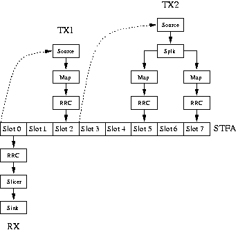
The STFA on its own doesn't do anything. The mode of operation and the kind of mapping done over the air is defined by attaching chains to it. If a chain is attached to an input of the STFA, we talk about a transmit-chain, or TX-chain. A receive-chain or RX-chain is attached to the output of the STFA.
 |
|
Two transmit and one receive-chain as an example
(stfa_tx_rx_example.ps) |
In figure <ref>fig:stfa_tx_rx_example</ref> you see a picture of some example-chain. In the middle is the STFA that is responsible to alert all modules as soon as there is some data to proceed. Looking at the RX-chain, you see that it is very simple for the STFA to know when to alert the RRC-module of the chain. The right moment is when this slot has been received.
For the TX1-chain, the right moment to alert the source-module is
 . Unfortunatly the
 is not known in advance and might change during the run of
the software-radio. One way to tackle this problem is to put an upper
time-limit on the calculation-duration, and call the top-module that much in
advance. In the actual STFA-implementation,
 ,
so that the first module of the TX1-chain is called at the beginning of slot 0.
Another problem arises when we have constructs as in the TX2-chain
4). Although it
is not optimal (See <ref>future_stfa_chains</ref>), we applied the same
reasoning as with the TX1-chain, that is, we call the top module of the
TX2-chain two slots in advance. The disadvantage is, that the whole chain has
to finish in the time
 .
.
Overcoming the Time-Limits
In an ideal setup, you'll be able to calculate every slot in a frame fast enough, so that it can be sent on time over the air. Unfortunatly, this is not always the case. Sometimes you want to trade in some of the real-time with the possibility to do some more calculations than the time allows. The problem is different on the sending- and on the receiving side.
The only time you'd want to send a slot that takes a very long time to calculate is when you want to do repeated measurements on the slot. So what you can do is to calculate the slot once, and then send it again and again. You can do this by setting the notice-point not to the top-module, but rather to the RRC-module only. Like this only the pulse-shape will be done, taking care of an eventual desynchronisation between the two radios 5).
On the receiver side, the only reason for taking more than the allocated time
is about the same. But you may easily take up more time than
 , if
the total amount of all receiving chains is not bigger than one frame. If this
might be the case, then you can use the following command:
make_thread( rrc_id );
This means that every time the STFA has data that needs to be processed, it checks whether the chain is still working, and only notifies the top-module, if no work is done. If the chain is still working, the STFA doesn't send the request, and waits for the next frame to check back again.
Here at EPFL we use these two techniques to measure code-qualities, especially LDPC-coding schemes. It is important to us that we get an actual transmission, but analyzing 10 slots per second is good enough for our case.