<texit>\part{Architecture}</texit>

Overview
In this part you'll learn about the architecture behind the software-radio. If you're looking for a precise information, you may be better off by looking at the reference-part of this document.
 |
|
The three main components and their respective subdivisions
(architecture_overview.ps) |
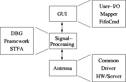
We like to split the software-radio in three parts: GUI, Signal Processing and the Antenna, as can be seen in figure <ref>fig:architecture_overview</ref>. For each of these elements, you can find a chapter that describes it in more detail. Additionally to these aspects, there are more general ones that don't fit that nicely into the pictures. Here is an overview of the chapters in this part of the documentation:
- GUI Is the Graphical User Interface, that allows to interact with the software-radio on a user-level
- Signal Processing is the ensemble of all interchangeable participants that make the active part of the software-radio
- Antenna represents the transmission and reception part of the software-radio, either in simulation or in real-time mode
- Operating system how the different parts of RTLinux and linux play together
- Modes of Operation gives an overview of the different modes of the software-radio
- Hardware which shows the architecture of the ICS-hardware
- Code the different directories in the tar-ball of the software-radio
GUI
<texit>\index{Visualize!Architecture|(}</texit> For taking measurements and changing the behaviour of the software-radio we developed this Graphical User Interface, called Visualize. It is capable of showing the internal states of all active modules (parts of the software-radio), their signals and changing the configuration of these modules while the software-radio is running.
By looking at figure <ref>fig:architecture_overview</ref>, we distinguish three main-parts of the GUI:
- User I/O is the input and output towards the user. It shows the chains, updates the statistics and offers windows to configure the modules
- Mapper arranges the modules in the software-radio to chains
- FifoCmd interfaces with the software-radio
User I/O
<texit>\index{Visualize!User I/O}</texit> Different ways of interfacing the software-radio exist. The user can display:
- Chains which is an overview of the general state of the software-radio
- Stats representing internal values of the modules, single values or plots
- Output-ports that are the signals that pass from one module to the next
- Plots tracing stats of different modules against each other or in time
There exist two ways of actively interacting with the software-radio:
- Re-configuration by changing parameters of one or more modules
- Process Data which informs a module to immediately do something by processing it's input
Chains
When the Visualize-tool is started, it displays an overview of all active chains for the first antenna of the first radio it finds. In fig. @screenshot of visualize start-up@ you see the STFA in the middle, surrounded by a sending and a receiving chain. Each module in the chain has its name displayed, as well as up to two parameters of its internal state.
Stats
A stats can either be a single value or a block of values. Examples of single values include SNR, variance, BER or counters, while blocks of values can include channel-vectors, slots or a whole frame.
Output-ports
Each module has zero to many output-ports that can be displayed in a seperate
window. As these signals can be of complex nature, one can chose to display
only the real, only the imaginary, or the absolute part. Additionally, one
can chose to display the FFT of the first
 samples
of the signal.
Plots
You may also be interested in a plot of one stats-variable in time or of two stats-variables one against the other. The Visualize-tool opens each new plot in a seperate window.
Export
All plotting-windows can be exported either as postscript-file or as a Matlab-function (which are also compatible with Octave).
Re-configuration
When asking for a re-configuration window, the Visualize-tool will update the software-radio with every new value you fill in. This is very useful for educational and debugging purposes.
Process-Data
This is mainly a debugging-function and allows to send a Data-msg to one of the modules, which will then process whatever is in its input.
Mapper
<texit>\index{Visualize!Mapper}</texit> This is an important part of the Visualize-tool, as it's not a straightforward task to identify chains and display them correctly. It is basically the original version written by two 4th year students, but extended to work with more than one STFA, or other main-modules.
FifoCmd
<texit>\index{Visualize!FifoCmd}</texit> This is the interface to the software-radio and takes care about the communication between the two. Everything is driven by the Visualize-tool, which means that the software-radio does only reply to requests from the GUI and never initiates a request by itself. <texit>\index{Visualize!Architecture|)}</texit>
Signal Processing
<texit>\index{Signal Processing!Architecture|(}</texit> Our goal was to find a suitable tradeoff between code re-use and performance of the software-radio. This is why we chose to have a modular framework, running on a RTLinux-platform. In the following sections, you will learn about the following items:
- DBG the interface to the GUI
- Framework which makes it possible that modules can interact with each other and the outer world
- STFA the interface to the channel
DBG
<texit>\index{Signal Processing!DBG}</texit> The debug-interface allows the user to interact with the software-radio. It accepts commands and queries from the GUI1) and replies accordingly. Looking at figure <ref>fig:architecture_dbg</ref> you can see the Fifos used in both RF- and simulation-mode.
 |
|
The debug-interface in RF- and simulation-mode
(architecture_dbg.ps) |
The replies of the dbg-module can be either status-informations or data directly from the software-radio. An overview of the different queries/replies can be found in <ref>chap:dbg-interface</ref>.
Framework
<texit>\index{Signal Processing!Framework|(}</texit> The modules, which define the specific task of the software-radio, are surrounded by a framework that takes care of the book-keeping tasks necessary to guarantee a good working together of the different modules.
There are three parts:
- Modules and Chains the specific description of different signal-processing parts, like pulse-shape filter, coding, mapping, and others
- CDB Class Data Base, where a reference to every available module is stored
- SDB Subsystem Data Base, which contains a reference to every instantiated and thus active module, as well as the glue that makes it work
Because of the complexity of the subsystem alone, it has its own subsection where an overview of its capabilities is shown. The same goes for the STFA.
Modules and Chains
<texit>\index{Signal Processing!Modules and Chains}</texit> The communication system is built out of modules. Each of the modules has a classroom-style function. As an example, in a simple one-way communication system, the transmitter could consist of a first module that maps bits into signal space points and a second module that maps signal space points into samples. In the corresponding receiver you may find a module that implements the matched filter, and another module that decides what was transmitted.
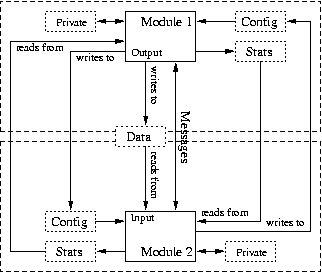
Signal processing modules have inputs and outputs for the signals being processed. They also have a configuration-part to control the behavior of the module (e.g. the desired amplification for an amplifier) and statistics to display relevant information (e.g. internal variables). This is shown in fig. <ref>cap:Two-simple-chains</ref>.
 |
|
Two simple chains and a module in detail
(modular.ps) |
Each of the modules can exist in multiple copies. The framework (composed of CDB and SDB) makes sure that each copy can work independently of the other copies, not unlike the class/instance-behaviour of C++ or other object-oriented languages.
When one or more modules are linked together, we speak about a chain of modules. The software-radio knows how to pass the data from one module to another, and will call each module at the appropriate time, that is when it has some data to process.
CDB and SDB
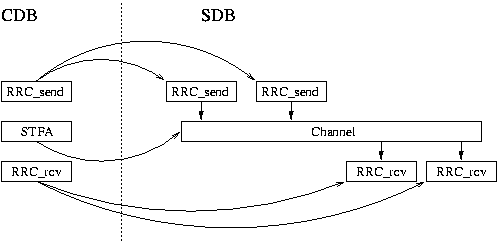
<texit>\index{Signal Processing!CDB}</texit> <texit>\index{Signal Processing!SDB}</texit> <texit>\index{CDB!Architecture}</texit> <texit>\index{SDB!Architecture}</texit> The Class Data Base (CDB) and Subsystem Data Base (SDB) make it possible to use the modules in an object-oriented approach. While the CDB holds the static information about a module, such as the names and types of the configuration-parameters, the SDB holds an actual implementation of a module, with the specific configuration-values that may differ from one implementation to another.
 |
|
The CDB and SDB
(cdb_sdb.ps) |
An overview of the CDB and SDB can be found in fig. <ref>fig:cdb_sdb</ref>. It shows part of a running software-radio that has two transmitting and two receiving slots2). On the left side you see the CDB that holds a description of each module that has been loaded in the software-radio. On the right-hand side, you see the actual instantiations of some modules present in the CDB.
The loading of the modules happens usually at start-up, but theoreticaly it's also possible to load further modules once the software-radio has been started. While loading, a module informs the CDB about it's presence, and includes the input/output signal-types, it's name, configuration and statistics-names and -types. After that, the module is inscribed in the CDB, but not yet not active.
Once a module is needed in the software-radio, it is instantiated, that is, a running instance of the module is created. This includes reservation of memory needed for the different variable parts, as well as initialisation of these parts. After a module is instantiated, it can be connected to other modules and can perform signal processing.
Subsystem
<texit>\index{Signal Processing!Subsystem}</texit> Usually the subsystem is a part of the SDB. But over time it has become quite complex and would deserve an own directory in the Base/-directory 3). One can think of the subsytem as the base-class for all modules. It offers a handful of virtual functions that allow it to interact with the modules.
The main goal of the subsystem is to allow interaction between two modules. In figure <ref>fig:architecture_subsystem</ref> all the possible interactions between two modules are shown.
 |
|
Two modules and all possible connections
(architecture_subsystem.ps) |
It is thus responsible for the following tasks:
- Allocating Memory for the Data, Config- and Stats-blocks
- Messaging between modules and do most tasks
- Threading the modules if necessary
Most changes in the state of a module include a message sent to the attached modules. An overview and short description of every message can be found in <ref>sec:sp_subsystem</ref>.
STFA
<texit>\index{Signal Processing!STFA}</texit> The Slot To Frame Allocator (STFA) is a module that makes the connection between the antenna and the rest of the modules. It offers a frame-based, slotted TDD interface to the rest of the signal-processing modules.
There exist two STFAs, one for the old hardware and one for the new, ICS-based hardware. The first is called stfa, while the second is called stfa_ics. <texit>\index{Signal Processing!Framework|)}</texit> <texit>\index{Signal Processing!Architecture|)}</texit>
Antenna
<texit>\index{Antenna!Architecture|(}</texit> The antenna-part of the software-radio has the structure as shown in fig. @Antenna-blowup: Common/Driver/HW/Server@ Their respective functions are as follows:
- Common is the interface towards the signal processing part
- Driver implements a certain hardware or simulation
- Hardware or Simulation the actual transmission system
Common
<texit>\index{Antenna!Common}</texit> The interface of the antenna offers the following parameters to the signal-processing part:
- DMA-region a place where the received samples are written to and the samples to be sent are read from
- RF-parameters frequency, amplitude and other config-parameters
- Timing an function is available that tells about the actual timing of the RX/TX part
Driver
<texit>\index{Antenna!Driver}</texit> This is the implementation of a certain way to transmit and receive samples. It has to take care about all initialisations and correct handling of all exceptions. The following drivers are functional:
- RF interfaces the old, STMicroelectronics based RF-system
- ICS interfaces the new, ICS-based RF-system that is capable of MIMO-transmission
- Simul for simulations of the RF-system
- Simul_ics for simulations of the ICS-system
- Emul does a simple copy of the data to be transmitted to the next slot
- NOP does nothing, for debugging purposes
Hardware or Simulation
The final part of the software-radio defines the channel. The Emul driver, for example, implements a flat single-tap channel with no noise. The Simul drivers need a channel-server that takes multiple radios together, mixes their signal, and sends back the calculated signal.
The most interesting parts are the RF and ICS hardware, because they offer a real channel to test the transmission with.
Hardware
<texit>\index{Antenna!Hardware}</texit> In the following table you can find a comparison of the two hardware-systems available. <texit>\begin{center}</texit>
| RF | ICS | |
| Max. number of antennas | 1 | 4 |
| Frequency [GHz] | 1.9 | 2.4-2.48 |
| Bandwith [MHz] | 3.8 | 1 |
| Resolution | 12 | 14 |
<texit>\end{center}</texit>
Simulation
<texit>\index{Antenna!Simulation}</texit> In simulation-mode, a channel-server accepts connections from different radios, as can be seen in fig. @channel-server with two radios@. The channel-server can simulate multi-tap channels and add gaussian noise to the transmitted signals. This allows for easy simulation of real-world signals, before taking the modules on the air. <texit>\index{Antenna!Architecture|)}</texit>
Operating System
<texit>\index{Operation System}</texit> One very important aspect of a software-radio is it's real-time capability. In our implementation, we transmit and receive slots of a duration of about 1ms. If we want to make sure that there is no blank in the transmission, we need to make sure to do our calculations in this short time-span and to do it at the right moment.
In a modern operation system, lots of things are happening at the same time: graphics, sound, network, disk-access and more. A normal program will have to wait for these tasks to finish, before it can do it's work. This means that it's nearly impossible for a normal program to meet sub-ms precision. Different approaches exist to bring a solution to this problem. We chose RTLinux because of it's stability, availability and because it is licensed under the GPL which means that other people can use this solution without having to pay high software-costs.
In short, RTLinux allows to meet time-constraints of a couple of
 , the precision-constraint that is given by todays hardware. It does
this by running a real-time aware micro-kernel which is principally
responsible for scheduling. One of the default tasks that runs with the
lowest priority is the linux-kernel. This makes sure that even if the
kernel is busy doing one of the not-so important things, RTLinux may
put it to sleep, execute the real-time task, and resume the
linux-kernel.
Modes of Operation
<texit>\index{Modes of Operation|(}</texit> As the signal-processing part and the framework is very flexible, different operating-modes are possible:
- Test which includes just a simple chain that is run a limited number of times
- Simulation or Real-Time modes which are possible for both Local-Loop and the Two-Radio System
- Local-Loop where a radio 'talks' to itself by receiving every sample sent
- Two-Radio System a set of two radio, where each one talks to the other
In the following sections, the advantages of each of these are listed.
Test
<texit>\index{Modes of Operation!Test}</texit> As the name indicates, this is used to test the basic functionality of a module. Usually it includes a simple chain that has only the most basic components in it in order to test the module. Like this one can test the module in a simple environment, before going through the more real and more complete test in a real-time communication.
To test a mapper-module that maps bits into complex symbols, it would be enough to have the chain as depicted in fig. @show modules: source→mapper→block→slicer→sink@ For convenience, the source can contain readable text-messages that are printed by the sink and can be verified by hand.
The block module exists in different variants, where MIMO channels and multi-tap fading channels can be simulated, both in a convenient, deterministic manner.
Simulation or Real-Time
<texit>\index{Modes of Operation!Simulation or Real-Time}</texit> As already described in section <ref>sec:HWorSimul</ref>, the software-radio can be run either locally without the RF-hardware and in a user-space mode, or it can be run in real-time using special RF-hardware for transmission and reception. While the former is much more easy to debug, only the latter allows to make real-world measurements and confirmation of theoretical results.
In the software-radio, both modes are transparent to the user, as the decision between the simulation or the real-time mode only has to be taken when running it. For the user, in either case, the channel is represented by the STFA.
Local-Loop
<texit>\index{Modes of Operation!Local-Loop}</texit> Sometimes it is too complicated to take care about all the synchronisation and fading-problems. Then you can chose to run your modules to test in a local-loop, and thus always be synchronised. When running in simulation-mode, the channel-server makes sure that the sent samples are received at the same time. If you run the radio in real-time mode, then you have to make sure to connect the output of the cards with the input through a cable.
Two-Radio System
<texit>\index{Modes of Operation!Two-Radio System}</texit> <texit>\index{Two-Radio System}</texit> TODO: update for ICS-example
This section describes a basic system with two radios, following the example of the radio found in Radios/Simple/BS and Radios/Simple/MS. It is important to know about this if you want to do more than just run the examples. You will learn about the most important modules, how to put them together and what make the thing going.
Setup
<texit>\index{Two-Radio System!Setup}</texit>
 |
|
The most simple two-way communication example
(simple_setup.ps) |
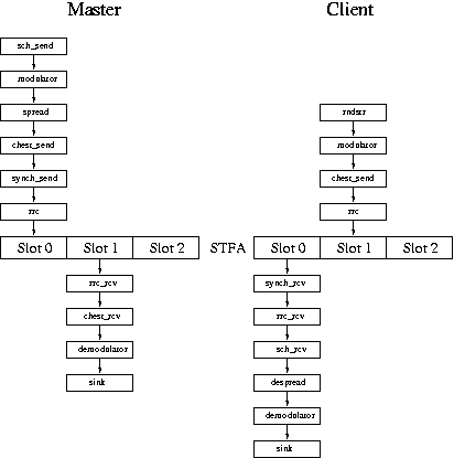
Looking at fig. <ref>cap:The-most-simple</ref>, you can see two parts: a master and a client 4). The communication channel in this example consists of three slots, of which only two are occupied 5). The part in the middle, where the tree slots reside, is called STFA, which means Slot To Frame Allocation. This is the most basic module that you will find in mostly all of the software-radio. The input of the STFA are sent through the antenna, while the received signal from the antenna is passed through the output of the STFA. As you can see in figure <ref>fig:architecture_overview</ref>, the antenna is a placeholder for either a real channel or just a simulation.
Modules
<texit>\index{Two-Radio System!Modules}</texit> This is a short overview of the different modules:
- sch_send
- Synchronisation CHannel. This module generates data that is used to communicate the configuration of the other clients. This includes the configuration about which slot to use for sending, which slot to use for receiving, and gain-control. Most of it is not used in a two-radio case.
- modulator
- Takes bits as inputs and creates complex symbols. In its default-configuration, it outputs QPSK symbols.
- spread
- Spreads the input-symbols with a given sequence. Usually this is used to have more than one radio sending during the same slot, in this example it is used to give some protection to the data, as a spreader may act as a simple coder.
- chest_send
- Inserts a training-sequence into the signal. This sequence is known at the receiver-end, which uses it then to estimate the channel and to create the matched-filter.
- synch_send
- Adds a synchronisation-sequence to the signal. The sequence is done in a special way so as to make it possible to retrieve the synchronisation-signal with as less calculation as possible.
- rrc
- The Root Raised Cosine pulse-shape filter. Takes the complex signal, upsamples by a factor of two and generates a real output.
- stfa
- Slot To Frame Allocation, takes the slots and prepares them to be sent over the channel.
- rrc_rcv
- Applies again a Root Raised Cosine filter
- chest_rcv
- The counterpart to chest_send, calculates the channel-estimation and the matched-filter, and applies it to the input-signal.
- demodulator
- Makes a hard decision on the received signals.
- sink
- Prints to the screen the received sequence of bits.
- synch_rcv
- Keeps up the synchronisation with the master.
- despread
- Undos the operation introduced by the spreader, and offers a cleaner signal. As coding module this is suboptimal.
- sch_rcv
- Decodes the synchronisation-channel and sets the tx-amplitude according to it's information.
Master
<texit>\index{Two-Radio System!Master}</texit> The masters task is to send out the synchronisation-signal on it's slot 1, combined with the data-signal that tells an eventual client its required tx-gain. The tx-gain of the client is calculated with the power received on slot 2. If it is below a certain threshold, the master considers that no client is sending, and puts the tx-power to 0. If the receiving-power is above a certain threshold, the tx-gain is adjusted to what the master would like to hear. This task in fact is done automatically by the sch_send module.
Client
<texit>\index{Two-Radio System!Client}</texit> While the master is quite static, the client has to do lots more:
- Search for the synchronisation-signal
- Set up the synch-slot and uplink-slot
- Keep the synchronisation
The first point is necessary because the client doesn't know beforehand the time-frame of the master. So, in order to get it, the mobile sets up a synch_rcv module on each slot, and choses the one that has the highest probability of a successful synchronisation. After this, it updates the offset of the STFA, so that it is in synch with the master, and keeps one synch_rcv module active, to allow for further synchronisation. All this is done in a macro-module called macro_synch.
Once the primary synchronisation is achieved, it will set up some modules to decode and demodulate the synchronisation-channel, as well as set up a tx-channel on slot 2.
After this it has to keep up the synchronisation, because the master and the client don't have exactly synchronised clocks. <texit>\index{Modes of Operation|)}</texit>
Hardware
<texit>\index{Hardware!Architecture}</texit> The current hardware is composed of three parts, as can be seen in fig. @figure of layout with ICS-rx and tx, as well as RF-cards@ This setup is optimized towards a 4×4 MIMO-system at 2.4GHz.
Code
<texit>\index{Code!Architecture}</texit> Once you untar the SRadio-*.tar.gz file, you find a directory in the form of SRadio-1.0.06) under which all the code is placed.
Directory Structure
- Base
- CDB, SDB and the channel implementations are found here, as well as some general helping functions to the MSR.
- Conventions
- template files that can be copied to new projects and then be filled in
- Modules
- all user-written modules are found in here, put into different categories: Coding, Channel, Data, General, Macro, Signal
- Test
- simple chains that are used to test the basic functionalities of the modules
- Radios
- full-fledged two way transmission parts
- User
- place for all compiled user-libraries
- Kernel
- place for all compiled kernel-libraries
- Documentation
- where you find this manual as well as some presentations